Better than a box of coloured pencils. Well, almost ...
One of the best applications supplied in rom with your machine is Draw. It's very neat, simple, yet a particularly powerful drawing tool which uses vector graphics to define a picture.
However, the Draw application itself doesn't actually produce the shapes by itself - the Draw module (part of the operating system) performs the intricacies of drawing the shapes on the screen. This is one of the reasons why drawfiles are so widely supported - it's really rather easy to do.
A drawfile consists of separate objects, some of which are paths. These are stored in a format which can be passed directly to the Draw module, along with attributes such as line thickness and colour.
The Draw module always performs operations on paths, either outputting a new one or drawing (referred to as stroking) it on the screen.
A Draw path consists of several elements, each of which is from one to seven words long. An element is something like a line, a curve or a gap. The first word in an element specifies its type, and is followed by a variable number of parameters. See Table I and its notes for details of the elements available.
A path contains one or more subpaths. Each is started by a type two element (start subpath) and is ended by either a type four or type five element (end subpath). You should always end subpaths explicitly, even if it's the only one in the path. Look at the example programs for examples of paths.
Looking at the descriptions of the elements in the table, you may have wondered what units the coordinates use. The simple answer is whatever you want them to be in.
The Draw module uses no less than four coordinate systems. The paths are defined in user units converted into internal draw units, which are then stroked on to the screen using OS units. The conversion of user units into internal draw units is controlled by a transformation matrix, specified in transform units, explained below.
OS units are nominally 1/180th of an inch, and are what the VDU system uses - MOVE, DRAW and similar commands in Basic. Internal draw units are 1/256ths of an OS unit, and are stored in signed 32-bit words which gives a maximum size of around two kilometres. This is probably large enough for most purposes.
Transform units are fixed point numbers. This is like a floating point number - as in the floating point emulator - except that the sizes of the integer and fractional parts are fixed, and so are much faster to process.
Transform units divide a four-byte word into two 16-bit fields (two bytes each). The effect of this is that a transform unit is 2^16 (65536) times a real number, stored in an integer ... don't worry, this will all become clearer later.
As mentioned before, user units are whatever you like. However, you should be wary of making them too different from internal draw units as scaling and rounding errors may occur. This usually manifests itself as curves drawn as lines, but there's nothing to worry about in the normal range of magnifications though.
A typical application using the Draw module may want to magnify, change the aspect ratio and rotate a drawing, all at the same time. It would be a little slow to perform one operation after another on each path of a drawing, so it would be really useful to be able to do all these things in just one operation.
Luckily, the world of mathematics comes to our rescue with something called a transformation matrix. This can do any number of operations on a path all at the same time and is much quicker than other methods.
You can use a transformation matrix with every call to the Draw module to scale the user units into internal draw units, but you can also change the shape of the path at the same time.
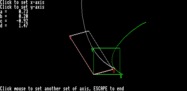
To see what you can do with matrices, look at Example1 from the Megadisk. A green path is displayed, which is the original path before transformation. Move and click the mouse to set the x and y axes, and then the transformed path will be drawn in white. Notice how the sides of the square lie along the axis you set, how its shape is distorted, and how the curve changes under the same transformation.

The matrix is specified as six numbers, imaginatively referred to as a, b, c, d, e and f, stored in consecutive words in memory. The 2x2 matrix (a, b, c and d) is in transform units and the translation coordinates (e and f) are specified in internal draw units to allow greater movement than a transform unit would allow - just 256 OS units, not very far.
The result of the transform is that a point (x, y) is mapped to a point (x', y') like this:
x' = ax + cy + e
y' = bx + dy + f
To transform a path, each point in every element of the path is run though the matrix.
The effect of the matrix is to alter the two axes of the path by effectively rotating them around (0, 0), so a point (1, 0), which lies on the x-axis, is mapped to (a, b), and a point (0, 1), which lies on the y-axis, is mapped to (c, d).
However, you needn't worry too much about this - Table II is a practical guide on how to use the transformation matrix.
To place your six numbers into memory to pass to the Draw module, use codes like:
DIM transform% 24
transform%!0 = a * 2^16
transform%!4 = b * 2^16
transform%!8 = c * 2^16
transform%12 = d * 2^16
transform%!16 = trans_x%
transform%!20 = trans_y%
a, b, c, d are floating-point numbers and trans_x% and trans_y% are the translation coordinates in internal draw units.
After all this, you may be wondering how to draw something on the screen. It's a lot easier than you might think. I'm going to cover the two main Draw SWIs: Draw_Stroke and Draw_Fill.
As with the Basic MOVE and DRAW commands, you first need to set the colour. You can use the GCOL command, but I would recommend using ColourTrans - see the panel for details on how to use ColourTrans.
Paths should be stored in a reserved memory area, claimed from Basic using the DIM command. For example, to reserve an area 1k long and place its address in path%, use the command:
DIM path% 1024
You then need to store the path in the array. To store a number in the nth word, use:
path%!(n * 4) = 42
Look at the example programs if you're not sure about this.
You use Draw_Stroke to draw a path on to the screen, and to draw the path stored at path% on the screen without using a transformation matrix - the path coordinates must be in internal draw units - use:
SYS "Draw_Stroke",path%,0,0,0,0,0,0
The six zeros tell the Draw module to use default settings for these parameters - I'll cover them later. To fill a path (draw it so that it's solid) use:
SYS "Draw_Fill",path%,0,0,0
Again, the zeros signify default parameters. If you want to draw a filled path with a different colour line around it, you will need to use Draw_Fill in one colour, change the colour and then use Draw_Stroke.
The Draw module can do more than just producing a thin line around the outline of a path and filling it in. If you've used the Draw application, you'll have seen how you can change the thickness of the line, specify how lines are to be joined, add arrow heads on the end of lines and even use dashed lines.
You'll not be surprised to learn that the Draw module does it all. The full form of the Draw_Stroke SWI is:
SYS "Draw_Stroke',path%,fill_style%,transform%,flatness%,line_thickness%,cap_join%,dash%
As in the first example of this call, all parameters except for path% can be set to zero to tell the Draw module to use the defaults.
You'll notice that this call takes a fill style. This does not mean it will fill the path as well - it specifies how thick lines are filled - the Draw module turns thick lines into filled shapes - I suggest you leave it as zero, the options it allows are rather esoteric.
The other items are:
transform% -
A pointer to a
transformation matrix
as described above.
flatness% -
A measure of how flat
curves are. The smaller
the value, the closer the
lines drawn will follow
the curve, and the less
jagged the curve will
look on screen,
Example3 shows this.
When stroking on to
the screen, I suggest you
let the Draw module
choose a suitable value
by setting this to zero.
line_thickness% -
Thickness of the lines
specified in user units.
The line is centered on
the edge of the path. If
it is zero, the line is
drawn one pixel thick.
cap_join% -
A pointer to a four word
block - see Table III for
its format. It must be
passed if line_thickness%
is anything other than
zero.
dash% -
A pointer to a dash
pattern. See Table IV for
its format. If you leave it
as zero, continuous
lines are drawn.

The Draw_Fill SWI is much simpler than Draw_Stroke and only takes four parameters:
SYS "Draw_Fill",path%,fill_style%,transform%,flatness%
The parameters are all explained above in the description of the Draw_Stroke SWI. As before, I suggest you leave fill_style% as zero.
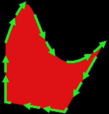
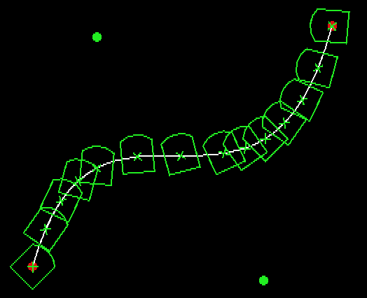
The MegaDisk contains some examples of the use of the draw module. Example1 and Example2 have already been discussed. Example3 shows some different path styles, and Example4 demonstrates some more advanced uses of the draw module.

The Draw module can do lots of other clever things, but unfortunately there isn't room to describe them all here. You'll just have to read about them in the PRM.
| Type | Parameters | Description |
| 0 | End of path | |
| 1 | ptr | Continuation of a path, ptr points to the first word of the next element |
| 2 | x y | Move to (x, y) starting a new subpath |
| 3 | x y | As type 2, but doesn't affect the winding rule. Mainly for the draw module's internal use. |
| 4 | Close subpath with a gap | |
| 5 | Close subpath with a line | |
| 6 | x1 y1 x2 y2 x3 y3 | Bezier curve (x3, y3) with control points (x1, y1) and (x2, y2) |
| 7 | x y | Gap to (x, y) |
| 8 | x y | Line to (x, y) |
In the following entries, m is the magnification factor, and theta
is an angle. Set m to scale your path to internal draw units, and
remember to multiply the numbers by 2^16 to turn them into transform units.
| a | b | c | d | Effect |
| m | 0 | 0 | m | Enlarge m times |
| m * cos(theta) | m * sin(theta) | m * -sin(theta) | m * cos(theta) | Enlarge m times, rotating it by theta anti-clockwise |
| m | 0 | k * m | m | Shear so (0, 1) maps to (k, 1), x-axis invariant |
| m | k * m | 0 | m | Shear so (1, 0) maps to (1, k), y-axis invariant |
| m * cos(2 * theta) | m * sin(2 * theta) | m * sin(2 * theta) | m * -cos(2 * theta) | Reflect the path in the line y = x * tan(theta) |
| Word offset | Byte | Description |
| 0 | 0 | Join style (0 = mitred, 1 = round, 2 = bevelled) |
| 1 | Leading cap style (0 = butt, 1 = round, 2 = projecting square, 3 = triangular (arrow head)) | |
| 2 | Trailing cap style (as leading cap style) | |
| 3 | Must be zero | |
| 4 | If you are using mitred joints, the mitre limit, in transform units | |
| 8 | If the leading cap style is triangular: | |
| 0, 1 | The width of the leading arrow head in 256ths of the line thickness | |
| 2, 3 | The height of the leading arrow head in 256ths of the line thickness | |
| 12 | If the trailing cap style is triangular, the size of the trailing arrow head in same format as for leading cap style |
The dash pattern is a list of lengths in user coordinates. Whether the line is drawn for that length alternates on and off, starting with draw on - the first element is how long the first dash should be, the second how long the gap before the next is, and third the length of the second dash, and so on. The pattern is repeated as many times as necessary to complete the path.
The dash pattern hash a small header before the elements. The format of the
dash block is:
| Word offset | Description |
| 0 | Distance into dash pattern to start |
| 4 | Number of elements following |
| 8 ... | Elements, each one word |
ColourTrans provides a level of abstraction from the video hardware in your machine. You tell it what colour you want, using 24-bit colour values, and ColourTrans selects the closest colour currently available. If necessary, ColourTrans will dither two colours together to get a better match.
The ColourTrans equivalent to the Basic GCOL command is:
SYS "ColourTrans_SetGCOL",colour%,,,flags%,action%
where colour% is the 24-bit colour, specified in the form &BBGGRR00 (blue * 16777216 + green * 65536 + red * 256, with each colour intensity ranging from 0 to 255), flags% should be zero, but add 128 if you want to set the background colour, and 256 if you want ColourTrans to use dithering. action% is the GCOL action as in the Basic command.
Obviously it's best to use this command instead of GCOL even in Basic programs, because it ensures compatibility with all types of hardware.
Click here to download the example files
| Source: | Acorn Computing March 1994 |
| Publication: | Acorn Computing |
| Contributor: | Ben Summers |