DrawGen Basic is an easy way to create drawfiles from simple Basic programs. In the previous article, I described how to use simple commands to create various geometric figures, to print text, and to control the colour of the output.
The beauty of the DrawGen system is that the programs to create drawfiles are just ordinary Basic programs, with no special symbols etc. You can therefore calculate the parameters used to make the drawfile using any normal Basic keywords, variables, procedures or functions.
The only restriction when you use DrawGen Basic is that no variable should start with the word "Global_". This is because the DGBasLib procedures define variables which are used in other procedures; all these variables start with the word "Global_". So if you avoid this word in your own variables, you should be OK.
The programs described below are on the Archive monthly disc.
PROCOrigin(2.5,3.5)
PROCFillColour(red%)
PROCRectangleFill(0,0,5,4)
The rectangle would usually be drawn with its lower lefthand corner at (0,0), but if you run the program, you should see that the rectangle has been drawn at (2.5,3.5). This is because of the command PROCOrigin(2.5,3.5).
As with the Basic command ORIGIN, this moves the origin of all subsequent measurements by the amounts indicated. It's as if margins have been added to the lefthand and bottom edges of the page. This command can be useful in order to locate a complicated diagram more accurately, without changing the parameters of all the commands, e.g. to centre it on the paper.
PROCOrigin(1,1)
PROCMagnify(2)
PROCFillColour(red%)
PROCRectangleFill(0,0,3,2)
This has another new command, PROCMagnify(2). If you run the program you will see that all the subsequent measurements have effectively been multiplied by 2. This includes the parameters given in PROCOrigin. Every point is now twice as far from the bottom left corner of the page as it would have been.
The rectangle would have been 3cm by 2cm, but now the rectangle has a width of 6cm and a height of 4cm. Its lower lefthand corner would have been at (1,1) because of the PROCOrigin(1,1), but because of PROCMagnify(2), this will now be at (2,2). PROCMagnify is the same as the Zoom command in Draw - everything is magnified, including the margins.
PROCMagnify can be used with any parameter, not just integers. So the scale can be made smaller by using a parameter less than one; e.g. PROCMagnify(0.25) will produce a diagram with all measurements a quarter of the values indicated in the commands.
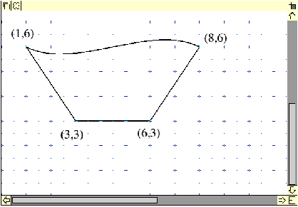
Let's look at a simple example of a program which draws a path. Look at Prog14. The first command is PROCStartPath(3,3). The parameters are the x and y-coordinates in cm of the point at which the path starts. The PROCDraw commands draw lines from the previous point to a new point at the coordinates given.
PROCDraw(6,3) draws a line from (3,3) to (6,3)
PROCDraw(8,6) draws a line from (6,3) to (8,6).
PROCDraw(1,6) draws a line from (8,6) to (1,6).
PROCEndClosedPath then draws a line from the previous point (1,6) back to the start point (3,3), thus "closing" the path.
Run the program. The result is as shown below (the coordinates of the points have been added to make the explanation easier to follow).

We could have put PROCEndOpenPath, but then that last line would not have been drawn. Try this.
Try changing the parameters of the PROCDraw commands. Add some more PROCDraws to make a more complex shape.
Put in PROCFillColour(red%) before the PROCStartPath command. Run the program. The shape you have drawn has been coloured.
PROCStartPath(3,3)
PROCDrawBy(3,0)      :REM to (6,3)
PROCDrawBy(2,3)      :REM to (8,6)
PROCDrawBy(-3.5,-1.5):REM to (4.5,4.5)
PROCDrawBy(-3.5,1.5) :REM to (1,6)
PROCEndClosedPath
It draws exactly the same figure as Prog14 did originally. Prog14 used the absolute coordinates of every point. Prog15 uses relative coordinates. The "By" after Draw shows that relative coordinates are used; e.g. PROCDrawBy(2,3) draws a line 2cm to the right, and 3cm up from the previous point. PROCDrawBy(-7,0) draws a line to a point 7cm to the left of the previous point. Experiment with both these commands. Using relative coordinates means that the whole figure can be moved just by changing the parameters of PROCStartPath.
PROCPolarDrawBy(d,theta)
and PROCPolarMoveBy(d,theta)
PROCPolarDrawBy draws a line from the current position to a point d away, at an angle theta to the positive x-direction. PROCPolarMoveBy is the same, but no line is drawn.
Prog16 shows PROCPolarDrawBy used to draw a polygon. The program has comments to explain the various steps. Note that you can change the variable sides% to any value. If you make it larger than 50, the polygon looks like a circle. Notice that the "origin" of the polar coordinates changes from vertex to vertex in Prog16. This is because of the "By" in the command PROCPolarDrawBy.
At other times, the 'origin' of the polar coordinates needs to remain fixed, especially where the figure has circular symmetry. Look at Prog17 as an example where the commands PROCPolarDraw and PROCPolarMove are used to draw cog-wheels.
These both use polar coordinates measured from the ORIGIN declared in PROCOrigin. The Origin is moved to the centre of each cog-wheel before starting to draw it.
Note also the use of PROCStartGroup and PROCEndGroup which enclose the drawing of the outline of a cog and the inner circular hole. Any figures or paths can be grouped together like this.
PROCStartPath(3,3)
PROCDraw(6,3)
PROCDraw(8,6)
PROCCurve(6,7,3,5,1,6)
PROCEndClosedPath
PROCCurve is used to draw part of the path as a curve - see below.
The parameters of PROCCurve are a little complicated. The curve is called a Bezier curve, and the direction and amount of curvature are controlled by the position of the two control points.

After PROCDraw(8,6), (8,6) is the current position. PROCCurve draws the curve from this position to its last two parameters, i.e. (1,6). The control points are (6,7) and (3,5). As the curve is drawn to the left from (8,6), the first control point is above the straight line from (8,6) to (1,6) - so the curve bends upwards. The second control point is below the straight line, so the curve goes downwards.
The best way to see the control points is to load the drawfile produced into Draw, select the figure, press <menu>, go right from "Select", and click on "Edit". You'll see the control points drawn in yellow. You can move them by dragging with <adjust>. Notice the effect this has on the curve. You can have as many PROCCurve's as you like inside a path.
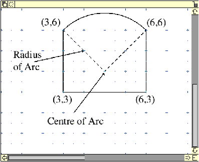
In PROCPathArc, neither the start position nor the end of the arc is defined explicitly - they have to be calculated. See Prog19 for an example of this - the drawfile produced is shown below.
Remember that the arc is always drawn anticlockwise; you must take this into account when you plan the drawing. Also, if you are going to add other draw commands after the PROCPathArc, then you have to put a PROCMove to the end-point of the arc first.
See Prog20 for an example which shows how a figure made up of two arcs must be drawn as two open paths. Note that, to appear to fill colour on the outside of the second arc, this arc must be filled with white. (PROCPathArc uses the same parameters as PROCArc, but this must be part of a path. PROCArc cannot be part of a path.)

You may, if you wish, change these default options by changing the !Run file.
Set DrawGen$Options -F3 -D1 -L5 -W12 -H12
The number after -L sets the default drawing line width in decipoints, in this case five decipoints.
-F3 specifies that three extra fonts are to be loaded.
-W12 and -H12 set the default font width and height.
-D1 specifies that the default font number is 1, i.e. the default Font is Homerton.Medium, 12 points wide and 12 points high.
Set DrawGen$ExFonts Corpus.Medium/Corpus.Medium.Oblique/Corpus.Bold
This lists the names of extra fonts to be included. (Maximum length of the variable is 256 characters. Note that names must be given exactly as listed in the font catalogue with '/' separators.) In this case, DrawGen$Options -F3 indicates that three extra fonts are to be loaded, and DrawGen$ExFonts shows they are: Corpus.Medium, Corpus.Medium.Oblique, and Corpus.Bold
| Source: | Archive Magazine 12.11 |
| Publication: | Archive Magazine |
| Contributor: | Brynmor Owen |